
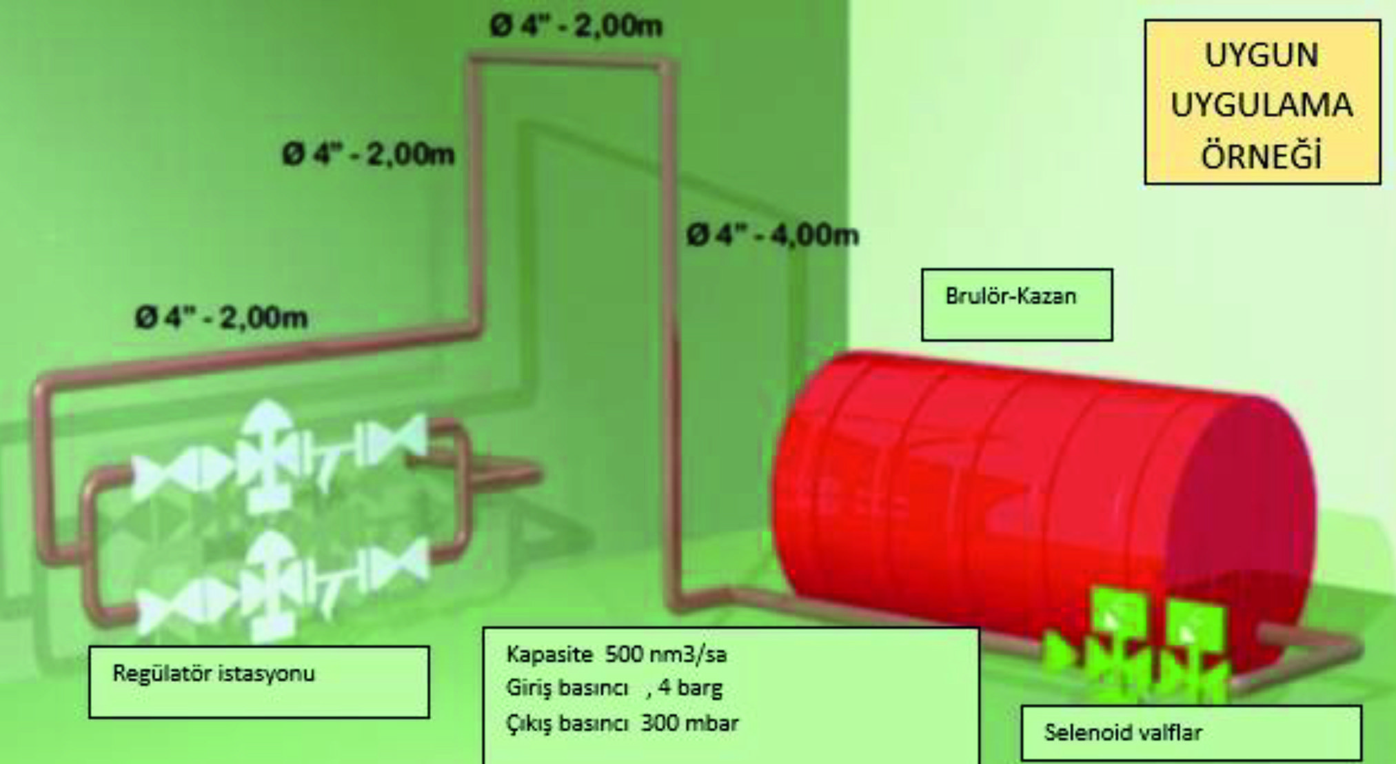
Pressure Shock and Its Effects Most ready-to-install industrial burners use surge solenoid valves in the gas lines. When these electric valves move from one position to another, they move quickly and create unusual shock pressures that can cause the pilot flame to go out, cause bad combustion, and shut down the system. Shock is defined in the dictionary as a sudden and strong shaking. As we know, shock in gas burner installations is the shock or pressure change caused by the sudden closing or opening of the solenoid valve. This shock can be positive or negative. In positive shock, the jolt of pressure increase is caused by the sudden closing of the solenoid valve. The gas regulator senses this increase in pressure, but if it cannot react quickly enough, excess pressure will enter the system between the regulator and the solenoid valve. If this pressure exceeds the upper limit setting of the slam-shut valve, the system shuts down. Not only will the gas flow be interrupted, the installed gauges will register a load higher than the designed range, causing the gauges to fail. In negative shock, when the solenoid valve opens rapidly, there is a sudden loss of system pressure. If the regulator cannot open quickly enough to increase flow and pressure, the low pressure that occurs during this delay may activate the safety shutoff. Temperature Effects As a rule, regulators should not be installed near the burner installation. Heat from the installation will radiate into the regulator and the temperature will cause the regulator's internal parts to exceed the given temperature limitations, causing leakage and subsequent system shutdown. Additionally, the increase in temperature will cause an increase in the set pressure and the shutdown of the system will be inevitable. Basic Rules to Be Considered in Creating the Installation; Below are the most important field-proven methods you can use to ensure the correct installation and proper operation of your burner system: • Choose the appropriate regulator • Use modulating solenoid valves • Verify meter specifications • Create adequate volume • Design your pipes correctly Regulator Selection A pilot-operated governor moves slower than a self-operated spring-type governor because governor movement depends on the movement of the pilot. Therefore, it is recommended to use a faster acting spring regulator in places where there are shock problems. Advantages of GHR Industrial Type Regulators; • High accuracy rate (RG 5) • Leak-proof closure (SG10) • Internal pressure relief valve (optional) • Integrated slam-shut (safety shut-off valve) • High flow capacity • Reduced noise • Easy maintenance and low parts cost Slam-Shut Valve Selection and Adjustment In order to completely cut off the gas flow in case of overpressure or underpressure output, regulation stations must be equipped with slamshut (safety shut-off) valves. To prevent undesirable release, these slam-shut valves must be adjusted in accordance with the system pressure and volume. Solenoid Valve Selection Great care should be taken in solenoid valve selection. The best way to eliminate shock problems is to use a modulating solenoid valve. This structure has a definite time delay when moving from one position to another, thus preventing sudden pressure changes in the system. Meter Selection Some meters have an operating frequency suitable for the spring regulator. In this case, the meter will create pressure vibrations in the pipe system. This resonance can combine with the frequency of the regulator and turn into higher and more sustained oscillations. The practical solution to this is to create separate lines for regulation and measurement. Meters should not be connected directly to the regulator output. Pipe Volume Adding volume between the regulator and the solenoid valve will provide better control under shock conditions. This should be done by increasing the pipe size, not the length of the pipe between the regulator and the solenoid valve. Volume Adding volume between the regulator and the solenoid valve will provide greater control under shock conditions. This should be done by increasing the pipe size, not the length of the pipe between the regulator and the solenoid valve. To ensure that the installation has sufficient volume between the regulator and the heater, a simple guideline can be applied (see table); where Qn is the nominal flow of the gas regulator in m3/h. P is the regulator outlet pressure. The required volume can, in most cases, be achieved with the available pipe volume; if this cannot be done, a volume tank must be installed. Basic Rules of Good Regulation; ✓ Do not oversize regulators, choose the smallest opening that will work. ✓ Always use the softest control spring possible, but if an imbalance problem occurs, a stiffer spring can provide and help maintain rigidity in the regulator. ✓ A regulator's moving parts can wear out or collect dirt depending on use. A sticking regulator can cause erratic control, appearing as imbalance. ✓ High flow rate may create noise. Noise can wear parts, which can cause instability. Keep regulator noise below 85 dBA. ✓ small volume outlet piping, always increase control precision. For small systems, place the regulator as far away from the burner as possible or install larger pipe. ✓ Do not use adjustment valves in control lines, use fully open ball valves. ✓ A regulator is a spring mass system and therefore has a natural frequency. It can react to other mechanical parts and volume of the piping system. ✓ Oscillation amplitude and frequency are a sign of imbalance. Get expert help and register if possible. ✓ Use control lines equal to or larger than the regulator signal size provided by the manufacturer. ✓ Do not place regulator signal lines immediately downstream of rotary or turbine meters. ✓ Keep regulator discharge lines open.


